 E-submission
 TOTA
TOTA TOTS
TOTS
Articles
- Page Path
- HOME > J Musculoskelet Trauma > Volume 38(3); 2025 > Article
-
Original Article
- Biomechanical finite element analysis of a femoral neck system fixation construct for femur neck fractures and clinical implications
-
Hoon-Sang Sohn, MD, PhD1
 , Se-Lin Jeong, BA2, Gu-Hee Jung, MD, PhD2,3
 -
Journal of Musculoskeletal Trauma 2025;38(3):133-142.
DOI: https://doi.org/10.12671/jmt.2025.00108
Published online: July 22, 2025
1Department of Orthopedic Surgery, Yonsei University Wonju College of Medicine, Wonju, Korea
2Institute of Health Sciences (Medical ICT Convergence Research Center), Gyeongsang National University College of Medicine, Jinju, Korea
3Department of Orthopedic Surgery, Gyeongsang National University Changwon Hospital, Gyeongsang National University College of Medicine, Changwon, Korea
- Correspondence to: Gu-Hee Jung, MD, PhD Department of Orthopedic Surgery, Gyeongsang National University Changwon Hospital, 11 Samjeongja-ro, Seongsan-gu, Changwon 51472, Korea Tel: +82-55-214-3822 Email: jyujin2001@hotmail.com
• Received: February 18, 2025 • Revised: April 14, 2025 • Accepted: April 17, 2025
© 2025 The Korean Orthopaedic Trauma Association
This is an Open Access article distributed under the terms of the Creative Commons Attribution Non-Commercial License (http://creativecommons.org/licenses/by-nc/4.0/) which permits unrestricted noncommercial use, distribution, and reproduction in any medium, provided the original work is properly cited.
- 3,278 Views
- 105 Download
- 1 Crossref
Abstract
-
Background This study assessed the structural/mechanical stability of fixation constructs with a femoral neck system (FNS) via finite element analysis after simulating femoral neck fractures and explored the clinical implications.
-
Methods We simulated subcapital, transcervical, basicervical, and vertical fracture models using a right femur (SAWBONES) and imported the implant model of FNS to Ansys (Ansys 19.0, Ansys Inc.) to place the implant in the optimal position. The distal end of the femur model was completely fixed and was abducted 7°. The force vector was set laterally at an angle of 3° and posteriorly at an angle of 15° in the vertical ground. The analysis was conducted using Ansys software with the von Mises stress (VMS) in megapascals (MPa).
-
Results The maximum VMS of the fracture site was 67.01 MPa for a subcapital, 68.56 MPa for a transcervical, 344.54 MPa for a basicervical, and 130.59 MPa for a vertical model. The maximum VMS of FNS was 840.34 MPa for a subcapital, 637.37 MPa for a transcervical, 464.07 MPa for a basicervical, and 421.01 MPa for a vertical model. The stress distribution of basicervical and vertical fractures differed significantly, and the basicervical fracture had higher VMS at the bone, implant, and fracture sites.
-
Conclusions FNS fixation should be performed with consideration the osseous anchorage in the femoral head, and this technique might be appropriate for vertical fractures. Regarding the VMS at the fracture site, FNS might be applied cautiously only to basicervical fractures with anatomical reduction without a gap or comminution.
-
Level of evidence IV.
Introduction
Considering that fracture site and orientation affect management modality and fixation construct in the treatment of young femoral neck fracture (FNF), trauma surgeons need convenient and reproducible standards to help them choose the best surgical implant and predict fracture-related complications [1,2]. Of FNFs in young adults, vertically oriented FNF (Pauwels type III) should be distinguished, because the high shearing force could explain the relatively high rate of nonunion and fixation failure [3-7]. It has been well established that anatomic reduction and choice of optimal implant are crucial for minimizing complications of FNF in young adults. Although the reduction adequacy was dependent on the surgeon’s experience and tactics, the implant choice is based on preoperative planning with an accurate assessment of fracture morphology, especially in high-energy injuries. These fractures are often stabilized with multiple cannulated screws (MCS), dynamic hip screws (DHS) with or without an anti-rotation screw [8-11].
Recently, the new minimally invasive implant femoral neck system (FNS; DePuySynthes) developed for dynamic fixation of FNFs. Owing to the advantages of angular stability with a minimally invasive surgical technique [12], the indications for FNS have been significantly broadened and have led to an increase in the use for various FNFs, although there is little evidence for clinical outcomes. Concerning the FNS implantation for highly unstable FNSs, there have been two main types of research: (1) retrospective analysis of clinical results and (2) biomechanical investigation enhancing the structural-mechanical stability [10,13-15]. However, few studies have measured biomechanical behavior according to the patterns of FNFs under the same conditions. Hence, by using the widely accepted finite element (FE) method [16-18], we would demonstrate the difference in structural-mechanical stability according to the patterns of FNFs and introduce the clinical implications of FNS.
This study did not involve human participants or animals, and therefore institutional review board approval was not required. A de-identified clinical image is included for illustrative purposes only, and informed consent was waived because no identifiable personal information is presented.
Methods
This study did not need approval by the Institutional Review Board, because its three-dimensional (3D) computer-aided design (CAD) model was from the commercially available high-resolution file of a right femur model: the standard fourth-generation composite bones (SAWBONES). Given the commercially available FNS, we modeled the 3D implant at actual size by using the 3D CAD software of SolidWorks 2019 (Dassault Systems SolidWorks Co.). Both the 3D femur and FNS were imported to SolidWorks for further polishing and were meshed using 1.0-mm tetrahedral mesh (Table 1).
The geometry of FE models corresponded to the definition of FNFs, including the subcapital, transcervical, basicervical [19], and vertical fractures [7]. The neck fractures were simulated in 3D CAD software of SolidWorks. Then, the 3D models of implant and femur were imported to the Ansys software (Ansys 19.0, Ansys Inc.) for placing the FNS in the optimal position and subsequently establishing the FE model by remeshing (Fig. 1). For FE analysis, the principles of model construction were uniform, as follows: (1) The plate with one hole made contact with the femoral diaphysis; (2) The trajectory of the screws was chosen based on the locking hole of the plate so that they protruded over 2 mm on the opposite side; (3) The contact between plate and screw was simulated as the bonding with virtual mechanical rigid links to mimic the locking head screw mechanism; (4) The bolt (screw) was inserted through the femoral head center or center-inferior at less than 10 mm in any direction from the outer boundary of the femoral head in concordance with the well-accepted technique of the manufacturer’s instructions [20].
The material properties for the synthetic femur were assigned according to the manufacturer’s specification for the fourth-generation SAWBONES (Table 1). We set the Young’s modulus of the cortical bone at 7,200 megapascal (MPa) with a Poisson’s ratio (y) of 0.350 and set it for the cancellous bone at 135 MPa with Poisson ratio (y) of 0.225. The density of the cortical bone was 1.5 g/cm3, and that of the cancellous bone was 0.2 g/cm [21,22]. All the metal of the implants was assumed to have the elastic, isotropic and homogeneous properties of titanium alloy in this study. The Young’s modulus of the titanium alloy was set at 96,000 MPa with a Poisson’s ratio (y) of 0.36 and the density of the implant was 4.62 g/cm [21].
The distal end of the femur model was completely fixed, and the loads of 1950 N, equivalent to tripling the body weight of the subject (65 kg), were applied to the center of the femoral head [23]. To mimic the normally physiologic alignment of lower limbs in the standing position, each assembly model was abducted 7° in the vertical ground (Fig. 1). The force vector was set laterally at an angle of 3° and posteriorly at 15°, because the femoral neck was slightly anteverted in relation to the position of the femoral condyles in the horizontal or transverse plane [24]. The 3D shear stress on the X axis was 98.57 N, 1947.3 N on the Y axis, and 26.4 N on the Z axis. We assumed that the implant was in direct contact with the bone (Table 1). According to the well-established and approved test contact setup method described in previous studies, a binding contact was formed between the internal fixation screw and the femur [25]. We could not evaluate the torsional results in these models. We assumed that the implant had direct contact with the bone and did the analysis using commercial FE software of Ansys with von Mises stress (VMS) in MPa, fracture displacement of the implant relative to the bone (as a measure of relative fixation strength).
Results
According to the displacement of the assembly model, the maximum displacement occurs at the upper part of the femoral head, as shown in Fig. 2. The displacements of the proximal femur were 9.28 mm for the no-fracture model, 9.61 mm for the subcapital fracture, 9.77 mm for the transcervical fracture, 9.86 mm for the basicervical fracture, and 9.87 mm for the vertical fracture. The VMS distributions on bone were assessed and are shown in Fig. 3. Compared with the no-fracture model, the subcapital and transcervical fracture had a similar distribution of VMS, which was the medial exit point of the screw through the plate (Fig. 4). The vertical fracture was the lateral insertion point of the plate. However, for the basicervical fracture, the max point of VMS was different from that in the other models and was in the posteromedial side of the fracture site (Fig. 5).
The max VMS of the fracture site was 67.01 MPa for the subcapital fracture, 68.56 MPa for the transcervical fracture, 344.54 MPa for the basicervical fracture, and 130.59 MPa for the vertical fracture (Fig. 6). For the stress distribution on the FNS, there were some differences based on the fracture morphologies. The max VMS of the implant was 840.34 MPa for the subcapital fracture, 637.37 MPa for the transcervical fracture, 464.07 MPa for the basicervical fracture, and 421.01 MPa for the vertical fracture (Fig. 6). For the stress distribution on the implant, the max points of VMS were the bolt around fracture site in all models and were in the junction site between the fracture site and the barrel of the plate (Fig. 7). There were two kinds of stress distribution of the bolt according to the fracture morphologies. The max point of the subcapital and transcervical fractures was the upper junction site, like that in the no-fracture model, and was the lower junction site for the basicervical and vertical fractures (Fig. 8).
Considering the max VMS distributions on the assembly models, the max VMS of the implant corresponded to the value of the entire fixation construct; so, the FNS mainly served for load-bearing, because the stress value of the fracture site was small except for the basicervical fracture. In terms of the load-bearing role, the implant’s VMS was the highest in the subcapital fracture and lowest in the vertical fracture. For the basicervical and vertical fractures, the stress distribution between the implant and fracture sites differed significantly; the basicervical fracture had higher VMS in the bone, implant, and fracture sites (Fig. 9).
Discussion
Although controversy remains regarding optimal fixation techniques and constructs, strategies for achieving optimal stability are crucial to minimizing the complications and sequelae in the management of high-energy FNFs. We conducted the FE analysis to assess the structural-mechanical stability of FNS in the nonosteoporotic FNFs. This computational analysis enabled us to arrive at several interesting findings. First, the max VMS of FNS corresponded to the value of the entire fixation construct and mainly functioned as the load-bearing implant. Second, for the subcapital and transcervical fractures, the stress distribution mainly concentrated on the implant and thus, the proximal osseous anchoring of the bolt might be necessary for maintaining rotational and angular stability. Third, the max VMS point of the fracture site was located on the posteroinferior side of the fracture site in the basicervical and vertical fractures. The VMS of the basicervical fracture was significantly larger than that of vertical fracture.
Although various implants exist for the operative fixation of FNFs, the use of FNS has been increased because of its biomechanical advantages with minimally invasiveness [12]. Thus, the surgical complications, including the cut-out, nonunion, and femoral head necrosis, inevitably have occurred [9,26]. To our best knowledge, there was no clinical report of FNS complications according to the fracture morphologies or Pauwels angle, although several studies have reported the comparative results of FNS and MCS [8-10]. Thus, considering these limitations of clinical case studies, we aimed to investigate the biomechanical behaviors of FNS based on the traditional classification of FNFs. Although it has been well established as most unstable fracture types, the VMS distribution of vertical fracture was similar to the no-fracture model but was much different from the basicervical fracture. The stress distribution of the fracture site was notably increased in the basicervical fracture. Thus, if the FNS fixation is considered for a basicervical fracture, the related factors of the variant types [27,28] and reduction adequacy, which are anatomically cortical contact, posteroinferior comminution, and fracture gap, should be verified intraoperatively before the definitive fixation. Because the vertically oriented fracture may contribute to the high failure rate in Pauwels’ grade III fractures in healthy young patient, the DHS with or without a de-rotational screw has been regarded as a superior fixation construct [4,29]. Before this investigation to identify the optimal indications, we anticipated that FNS may not be appropriate for vertical fractures, because it is a smaller implant of plate and lag screw (bolt) than is DHS. Although we did not analyze the direct comparison between FNS and DHS, our results demonstrated that the stress distribution of the fixation construct was concentrated on the implant and not the fracture site.
When compared between vertical fracture and basicervical fracture, the max VMS value of the implant was not significantly different, but it was much different at the fracture site. Thus, despite these prejudices, we think the vertical fracture might be more suitable for FNS fixation than the basicervical fracture. Furthermore, considering that 96% of vertical neck fractures had major comminution, which was mainly located inferiorly and posteriorly [30], the FNS for vertical fractures might be an appropriate implant for vertical fracture based on our results, which showed the lower stress distribution on the fracture site. Additionally, compared with the no-fracture model, the VMS distribution of the vertical fracture was most similar in the fracture site and implant. For the subcapital fracture, the stress distribution mainly concentrated on the implant, and the max points of VMS were the bolt around the fracture site. Based on this result, authors should assume that the anchoring between the proximal bolt and the cancellous bone of the femoral head is maximized. In the personal communication between orthopedic trauma surgeons, we found that fixation failure of FNS was not uncommon, although the critical factors could not be analyzed. However, this FE analysis seems to show that the proximal osseous anchoring of the bolt might be essential for maintaining rotational and angular stability. The subcapital fracture might be cautiously applied because the femoral head fragment had a short working length. Adding an anti-rotational screw to the FNS might increase the proximal anchoring and angular stability, so further research on this topic will be performed in the future (Fig. 10).
Despite interesting findings, this computational simulation study has several fundamental limitations. First, our fracture models were very simplified for simulating the perfect reduction without gap and comminution between fragments. Second, our results had descriptive characteristics because we used not patient-specific computed tomography-based bone models but synthetic bone models, which were simulated using a normal nonosteoporotic femur without considering the heterogeneous properties of real human bone. Third, the fracture impact by controlled sliding of the lag screw/blade could not be simulated, because of technical difficulties. Our results just showed the initial strength of the fixation construct. Nevertheless, our computational analysis could be assessed on structural-mechanical strength and the VMS distribution of the fracture site and the implant under the same conditions. Although the implant should be chosen in terms of the extent of displacement, fracture configuration, physiological age, bone quality, and other factors, our results might be able to directly suggest technical relevance to maximize the structural strength of the FNS fixation construct for FNFs. By utilizing previous research experience, we will conduct a comparative study of other fixation constructs, including the DHS, MCS, and intramedullary nails, in the future. Additionally, further research is needed to determine what makes the difference between basicervical fracture and vertical fracture fixed with FNS.
Conclusions
Based on the stress distribution of fracture sites and implants, the FNS fixation construct might be appropriate for transcervical and vertical fractures. For a basicervical fracture, an FNS might be applied in the anatomically reduced fracture without gap and comminution. For subcapital fractures, considering the high-stress distribution of the proximal bolt around fracture site, there are two important things; (1) The osseous anchorage of femoral head might be essential to maintain the structure-mechanical stability. (2) The working length of the bolt in the femoral head is verified preoperatively.
-
Author contributions
Data curation: SLJ. Formal analysis: HSS. Methodology: HSS, SLJ. Funding acquisition: GHJ. Supervision: GHJ. Visualization: SLJ. Writing-original draft: HSS, GHJ. Writing-review & editing: GHJ. All authors read and approved the final manuscript.
-
Conflicts of interest
None.
-
Funding
This research was supported by the grant from Institute of Medical Science of Gyeongsang National University, 2021.
-
Data availability
Contact the corresponding author for data availability.
Article Information
Fig. 1.

The neck fractures were simulated in three-dimensional (3D) computer-aided design software (SolidWorks 2019, Dassault Systems SolidWorks Co.). Then, the 3D models of the implant and femur were imported to Ansys software (Ansys 19.0, Ansys Inc.) in order to place the femoral neck fracture in the optimal position. (A) No fracture. (B) Subcapital F. (C) Transcervical F. (D) Basicervical F. (E) Vertical F.
Fig. 2.

According to the displacement of the assembly model, the maximum displacement occurs at the upper part of the femoral head. The displacement was the largest in basicervical and vertical fractures.
Fig. 3.
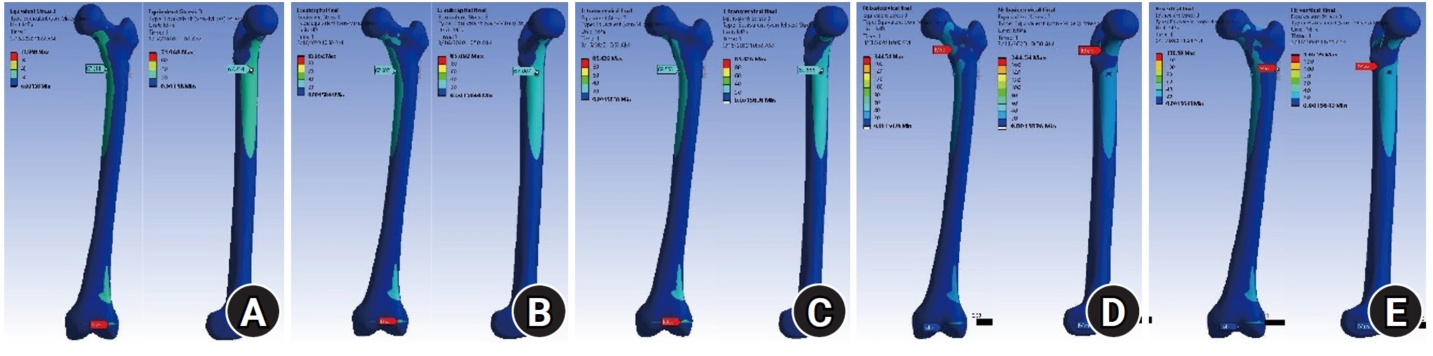
The von Mises stress (VMS) distributions on bone. Compared with the no-fracture model, the subcapital and transcervical fractures had a similar VMS distribution, which was the medial exit point of the screw through the plate. However, for the basicervical and vertical fractures, the max point of VMS was different from that in other models and was located in the medial side of the fracture site. (A) No fracture. (B) Subcapital F. (C) Transcervical F. (D) Basicervical F. (E) Vertical F.
Fig. 4.

Compared with the no-fracture model, the subcapital and transcervical fractures had a similar von Mises stress distribution, which was the medial exit point of the screw through the plate. (A) No fracture. (B) Subcapital F. (C) Transcervical F. (D) Basicervical F. (E) Vertical F.
Fig. 5.
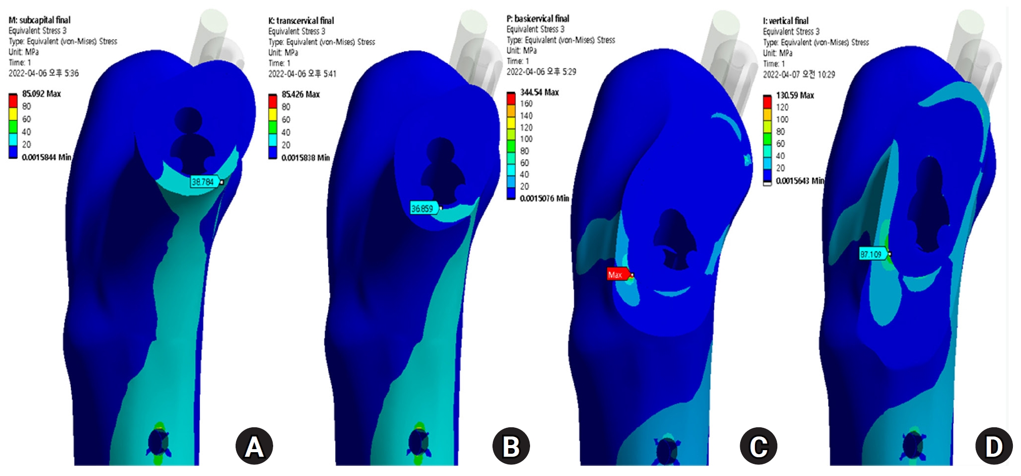
The stress distribution of the fracture site was notably increased in the basicervical fracture, for which the point with the maximum von Mises stress was different from that in other models and was located in the posteroinferior area of the fracture site. (A) Subcapital F. (B) Transcervical F. (C) Basicervical F. (D) Vertical F.
Fig. 6.
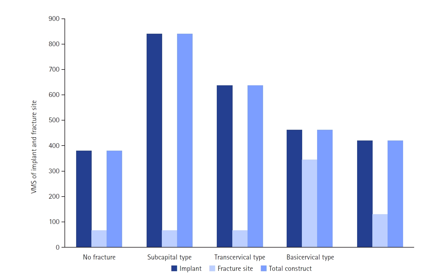
von Mises stress (VMS) of implant and fracture site. The maximum VMS of the fracture site was 67.01 megapascal (MPa) for the subcapital fracture, 68.56 MPa for the transcervical fracture, 344.54 MPa for the basicervical fracture, and 130.59 MPa for the vertical fracture.
Fig. 7.

For the stress distribution on the implant, the points with the maximum von Mises stress were the bolt around the fracture site in all models; it was located in the junction between the fracture site and the barrel of the plate. (A) No fracture. (B) Subcapital F. (C) Transcervical F. (D) Basicervical F. (E) Vertical F.
Fig. 8.
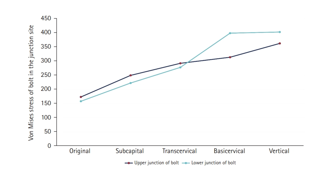
von Mises stress of bolt in the junction site. There were two kinds of stress distribution of the bolt according to the fracture morphologies. The maximum point of the subcapital and transcervical fractures was the upper junction site, as in the no-fracture model, and was the lower junction site for the basicervical and vertical fractures.
Fig. 9.
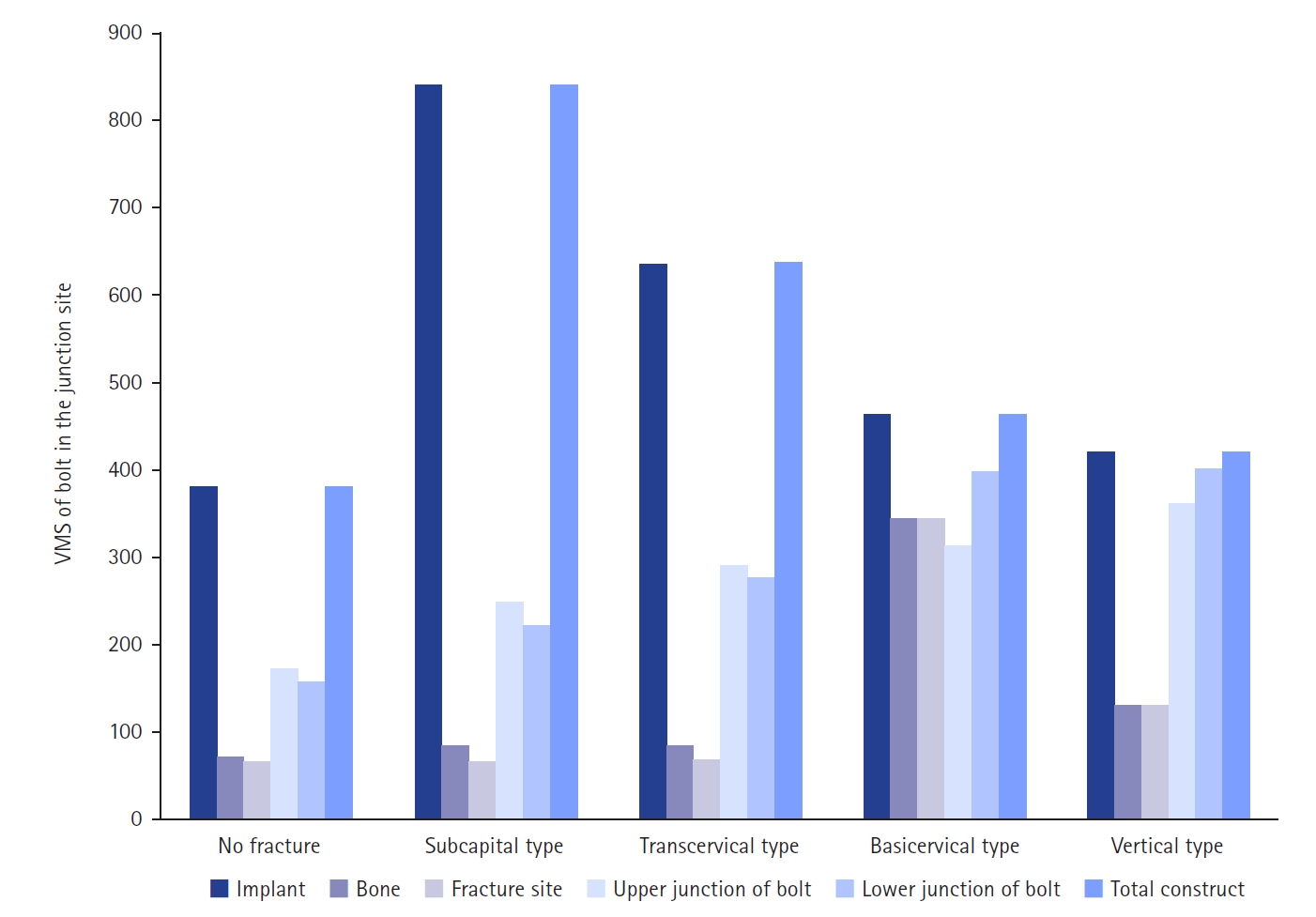
von Mises stress (VMS) of bolt in the junction site in terms of the load-bearing role, the implant’s VMS was the highest in the subcapital fracture and lowest in the vertical fracture. Comparing the basicervical and vertical fractures, the stress distribution between the implant and fracture sites differed significantly, and the basicervical fracture had higher VMS in the bone, implant, and fracture sites.
Fig. 10.
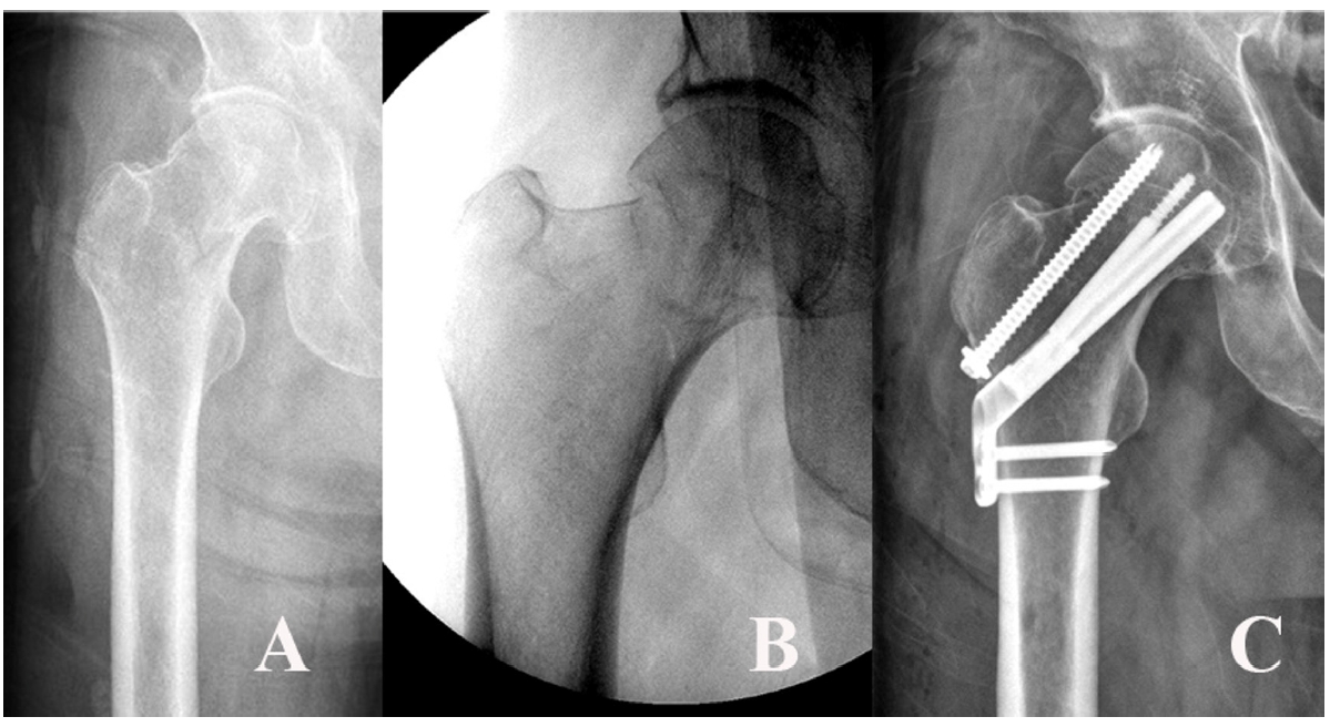
A 54-year-old male patient sustained a femoral neck fracture caused by a fall from a 2-m height. (A, B) Plain radiographs and an intraoperative fluoroscopic image show the subcapital fracture. (C) The femoral neck system anti-rotational screw was applied to increase the anchoring and stability of the femoral head fragment.
Table 1.
Material properties of bone and implant
| Material | Density (g/cm3) | Elastic modulus (megapascal) | Poisson’s ratio |
|---|---|---|---|
| Cortical bone | 1.5 | 7,200 | 0.35 |
| Cancellous bone | 0.2 | 135 | 0.225 |
| Titanium alloy (fixation implant) | 4.62 | 96,000 | 0.36 |
- 1. Shen M, Wang C, Chen H, Rui YF, Zhao S. An update on the Pauwels classification. J Orthop Surg Res 2016;11:161.ArticlePubMedPMCPDF
- 2. Kong GM, Kwak JM, Jung GH. Eliminating projection error of measuring Pauwels' angle in the femur neck fractures by CT plane manipulation. Orthop Traumatol Surg Res 2020;106:607-11.ArticlePubMed
- 3. Enocson A, Lapidus LJ. The vertical hip fracture: a treatment challenge. A cohort study with an up to 9 year follow-up of 137 consecutive hips treated with sliding hip screw and antirotation screw. BMC Musculoskelet Disord 2012;13:171.ArticlePubMedPMCPDF
- 4. Liporace F, Gaines R, Collinge C, Haidukewych GJ. Results of internal fixation of Pauwels type-3 vertical femoral neck fractures. J Bone Joint Surg Am 2008;90:1654-9.ArticlePubMed
- 5. Parker MJ. Results of internal fixation of Pauwels type-3 vertical femoral neck fractures. J Bone Joint Surg Am 2009;91:490-1.
- 6. Aminian A, Gao F, Fedoriw WW, Zhang LQ, Kalainov DM, Merk BR. Vertically oriented femoral neck fractures: mechanical analysis of four fixation techniques. J Orthop Trauma 2007;21:544-8.ArticlePubMed
- 7. Johnson JP, Borenstein TR, Waryasz GR, et al. Vertically oriented femoral neck fractures: a biomechanical comparison of 3 fixation constructs. J Orthop Trauma 2017;31:363-8.PubMedPMC
- 8. Tang Y, Zhang Z, Wang L, Xiong W, Fang Q, Wang G. Femoral neck system versus inverted cannulated cancellous screw for the treatment of femoral neck fractures in adults: a preliminary comparative study. J Orthop Surg Res 2021;16:504.ArticlePubMedPMCPDF
- 9. He C, Lu Y, Wang Q, et al. Comparison of the clinical efficacy of a femoral neck system versus cannulated screws in the treatment of femoral neck fracture in young adults. BMC Musculoskelet Disord 2021;22:994.ArticlePubMedPMCPDF
- 10. Zhou XQ, Li ZQ, Xu RJ, et al. Comparison of early clinical results for femoral neck system and cannulated screws in the treatment of unstable femoral neck fractures. Orthop Surg 2021;13:1802-9.ArticlePubMedPMCPDF
- 11. Chan DS. Femoral neck fractures in young patients: state of the art. J Orthop Trauma 2019;33 Suppl 1:S7-11.Article
- 12. Stoffel K, Zderic I, Gras F, et al. Biomechanical evaluation of the femoral neck system in unstable Pauwels III femoral neck fractures: a comparison with the dynamic hip screw and cannulated screws. J Orthop Trauma 2017;31:131-7.ArticlePubMed
- 13. Kuang X, Jian G, Xie D, Chen X, Liu H. Choose the appropriate implantation position of the femoral neck system in the femoral neck: a finite-element analysis. Eur J Trauma Emerg Surg 2023;49:1845-53.ArticlePubMedPMCPDF
- 14. Cha Y, Park S, Jung CH, et al. Additional screw added to the femoral neck system could enhance the stability of Pauwel Type III femoral neck fractures: a finite element analysis. Clin Orthop Surg 2025;17:204-15.ArticlePubMedPMCPDF
- 15. Nan C, Li Y, Liu Y, Ma L, Ma Z. Biomechanical comparison of femoral neck system and cannulated screws coupled with medial plate for treating Pauwels III femoral neck fractures. Technol Health Care 2023;31:1161-70.ArticlePubMed
- 16. Kluess D. Finite element analysis in orthopaedic biomechanics. In: Moratal D, ed. Finite element analysis. IntechOpen; 2010. p. 151-70.
- 17. Kwak DK, Kim WH, Lee SJ, Rhyu SH, Jang CY, Yoo JH. Biomechanical comparison of three different intramedullary nails for fixation of unstable basicervical intertrochanteric fractures of the proximal femur: experimental studies. Biomed Res Int 2018;2018:7618079.ArticlePubMedPMCPDF
- 18. Dragomir-Daescu D, Salas C, Uthamaraj S, Rossman T. Quantitative computed tomography-based finite element analysis predictions of femoral strength and stiffness depend on computed tomography settings. J Biomech 2015;48:153-61.ArticlePubMedPMC
- 19. Watson ST, Schaller TM, Tanner SL, Adams JD, Jeray KJ. Outcomes of low-energy basicervical proximal femoral fractures treated with cephalomedullary fixation. J Bone Joint Surg Am 2016;98:1097-102.ArticlePubMed
- 20. Stassen RC, Jeuken RM, Boonen B, Meesters B, de Loos ER, van Vugt R. First clinical results of 1-year follow-up of the femoral neck system for internal fixation of femoral neck fractures. Arch Orthop Trauma Surg 2022;142:3755-63.ArticlePubMedPDF
- 21. Song Z, Wang Q, Ma T, et al. Failure analysis of primary surgery and therapeutic strategy of revision surgery for complex tibial plateau fractures. J Orthop Surg Res 2019;14:110.ArticlePubMedPMCPDF
- 22. Bernard S, Schneider J, Varga P, Laugier P, Raum K, Grimal Q. Elasticity-density and viscoelasticity-density relationships at the tibia mid-diaphysis assessed from resonant ultrasound spectroscopy measurements. Biomech Model Mechanobiol 2016;15:97-109.ArticlePubMedPDF
- 23. Van Houcke J, Schouten A, Steenackers G, Vandermeulen D, Pattyn C, Audenaert EA. Computer-based estimation of the hip joint reaction force and hip flexion angle in three different sitting configurations. Appl Ergon 2017;63:99-105.ArticlePubMed
- 24. Bergmann G, Deuretzbacher G, Heller M, et al. Hip contact forces and gait patterns from routine activities. J Biomech 2001;34:859-71.ArticlePubMed
- 25. Sensoz E, Özkal FM, Acar V, Cakir F. Finite element analysis of the impact of screw insertion distal to the trochanter minor on the risk of iatrogenic subtrochanteric fracture. Proc Inst Mech Eng H 2018;232:807-18.ArticlePubMedPDF
- 26. Hu H, Cheng J, Feng M, Gao Z, Wu J, Lu S. Clinical outcome of femoral neck system versus cannulated compression screws for fixation of femoral neck fracture in younger patients. J Orthop Surg Res 2021;16:370.ArticlePubMedPMCPDF
- 27. Zhang Y, Hu J, Li X, Qin X. Reverse wedge effect following intramedullary nailing of a basicervical trochanteric fracture variant combined with a mechanically compromised greater trochanter. BMC Musculoskelet Disord 2020;21:195.ArticlePubMedPMCPDF
- 28. Shoda E, Kitada S, Sasaki Y, et al. Proposal of new classification of femoral trochanteric fracture by three-dimensional computed tomography and relationship to usual plain X-ray classification. J Orthop Surg (Hong Kong) 2017;25:2309499017692700.ArticlePubMedPDF
- 29. Ye Y, Hao J, Mauffrey C, Hammerberg EM, Stahel PF, Hak DJ. Optimizing stability in femoral neck fracture fixation. Orthopedics 2015;38:625-30.ArticlePubMed
- 30. Collinge CA, Mir H, Reddix R. Fracture morphology of high shear angle "vertical" femoral neck fractures in young adult patients. J Orthop Trauma 2014;28:270-5.ArticlePubMed
References
Figure & Data
REFERENCES
Citations
Citations to this article as recorded by 
- Finite element analysis of screw thread geometry and titanium plate materials in internal fixation of the human femur
Abdessamed Bachiri, Mustapha Amine Arab, Nadia Kadouri
Computer Methods in Biomechanics and Biomedical Engineering.2026; : 1. CrossRef
 ePub Link
 Cite
CiteBiomechanical finite element analysis of a femoral neck system fixation construct for femur neck fractures and clinical implications
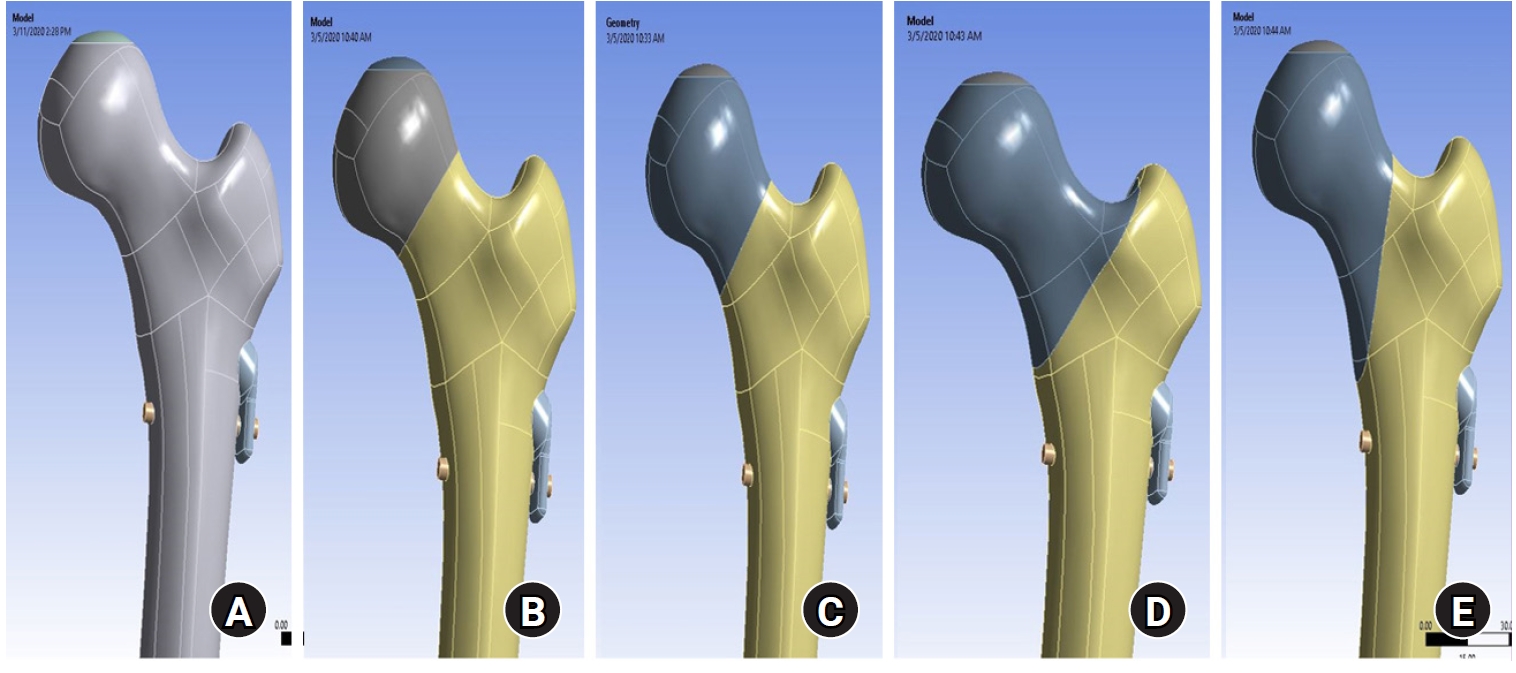
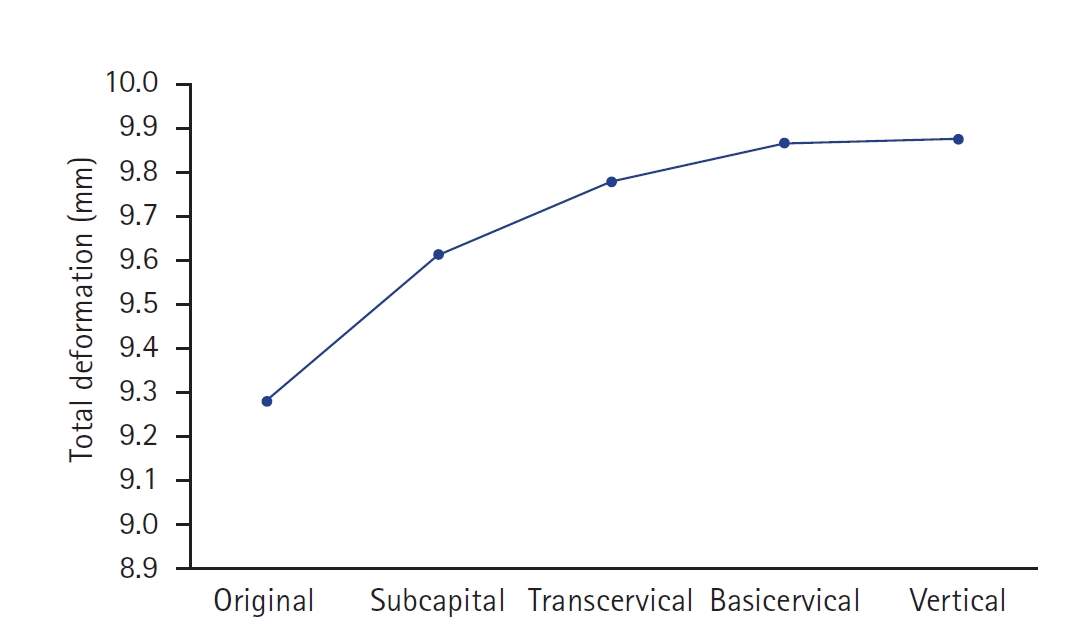

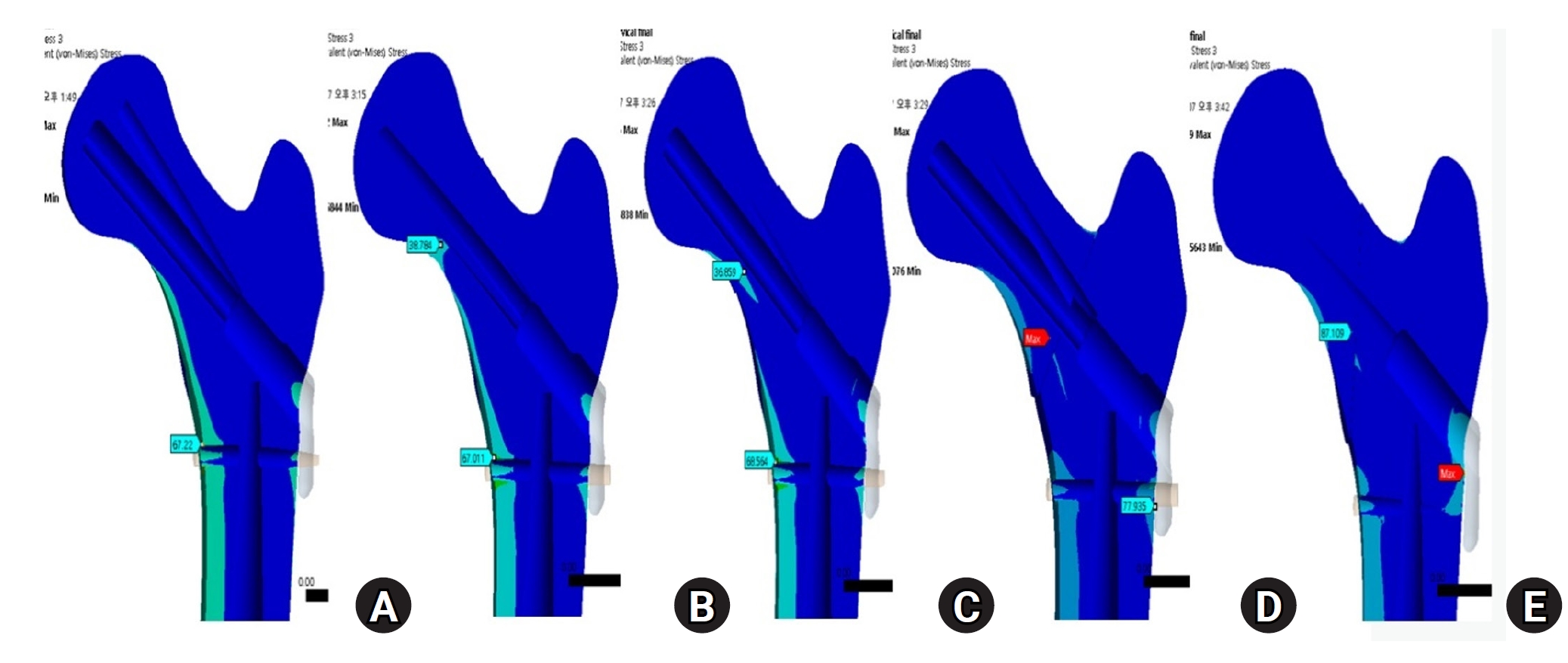

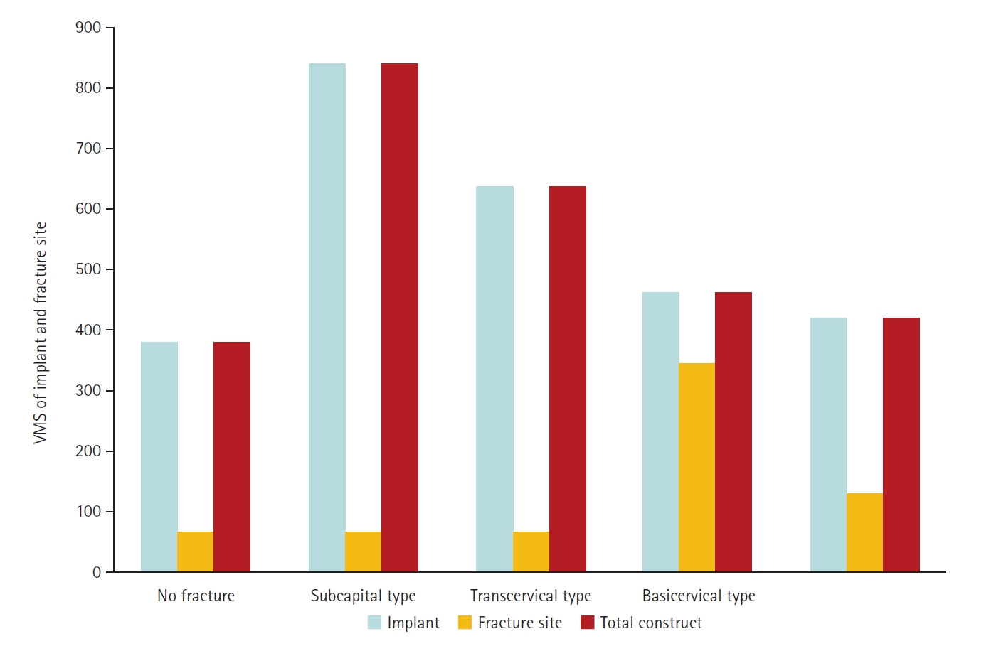
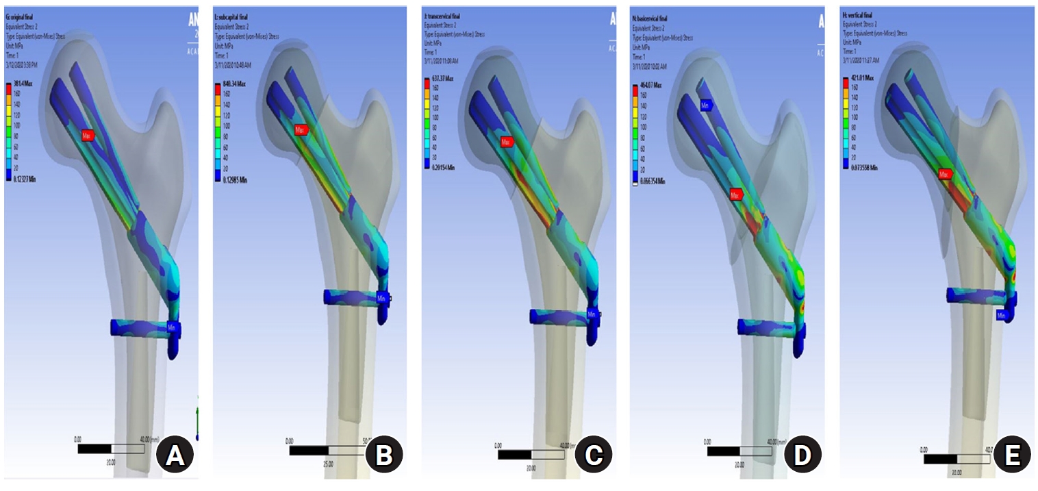
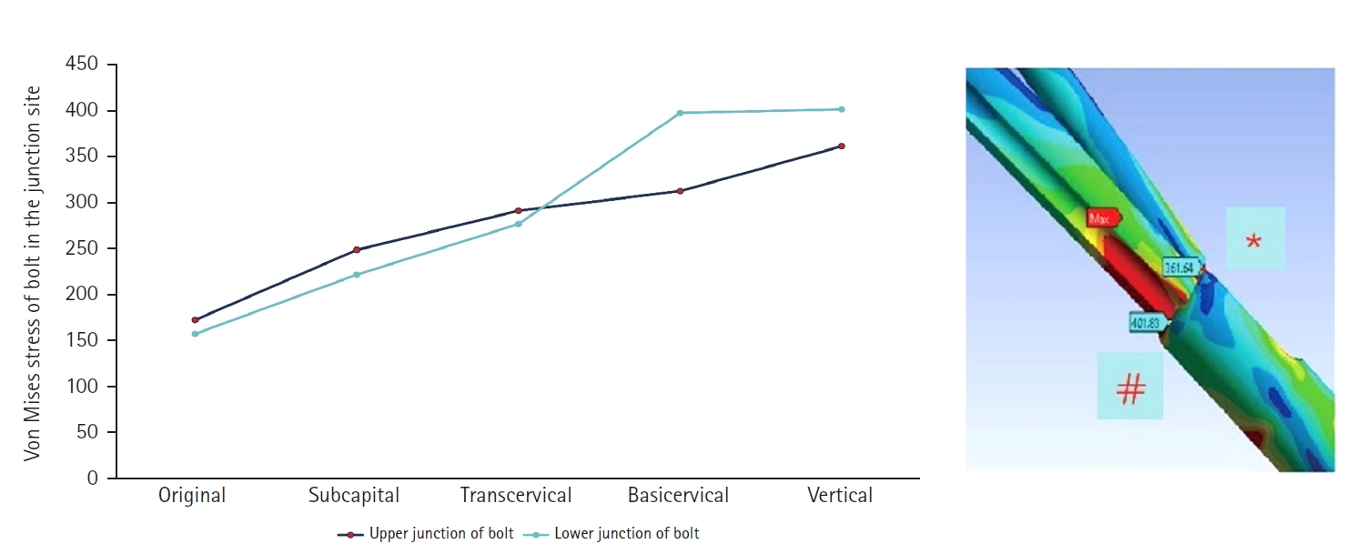
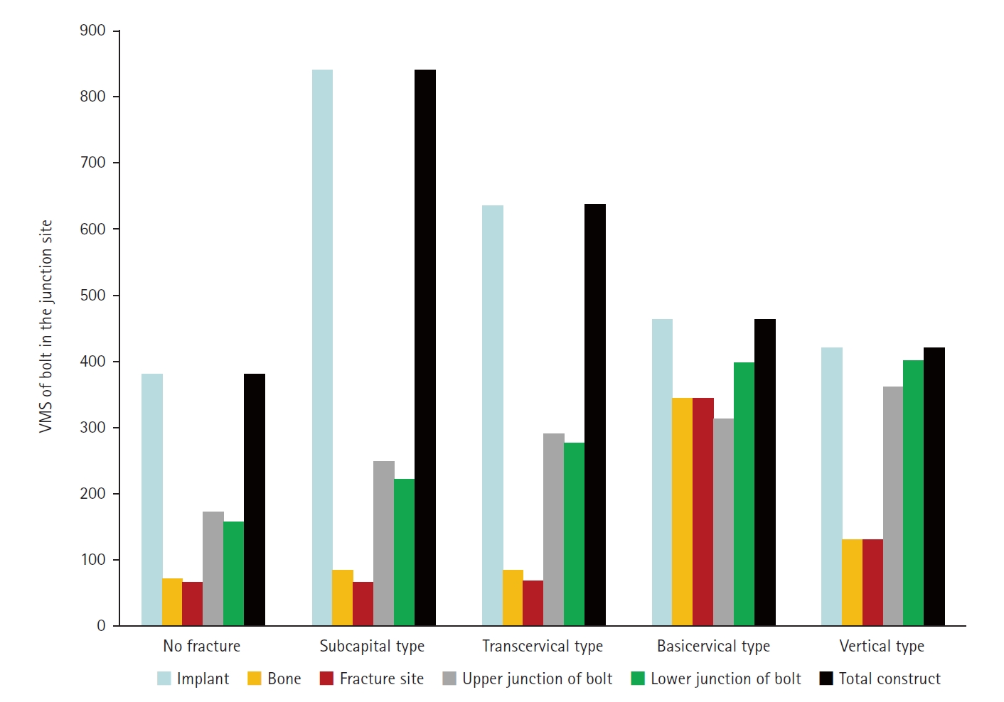

Fig. 1. The neck fractures were simulated in three-dimensional (3D) computer-aided design software (SolidWorks 2019, Dassault Systems SolidWorks Co.). Then, the 3D models of the implant and femur were imported to Ansys software (Ansys 19.0, Ansys Inc.) in order to place the femoral neck fracture in the optimal position. (A) No fracture. (B) Subcapital F. (C) Transcervical F. (D) Basicervical F. (E) Vertical F.
Fig. 2. According to the displacement of the assembly model, the maximum displacement occurs at the upper part of the femoral head. The displacement was the largest in basicervical and vertical fractures.
Fig. 3. The von Mises stress (VMS) distributions on bone. Compared with the no-fracture model, the subcapital and transcervical fractures had a similar VMS distribution, which was the medial exit point of the screw through the plate. However, for the basicervical and vertical fractures, the max point of VMS was different from that in other models and was located in the medial side of the fracture site. (A) No fracture. (B) Subcapital F. (C) Transcervical F. (D) Basicervical F. (E) Vertical F.
Fig. 4. Compared with the no-fracture model, the subcapital and transcervical fractures had a similar von Mises stress distribution, which was the medial exit point of the screw through the plate. (A) No fracture. (B) Subcapital F. (C) Transcervical F. (D) Basicervical F. (E) Vertical F.
Fig. 5. The stress distribution of the fracture site was notably increased in the basicervical fracture, for which the point with the maximum von Mises stress was different from that in other models and was located in the posteroinferior area of the fracture site. (A) Subcapital F. (B) Transcervical F. (C) Basicervical F. (D) Vertical F.
Fig. 6. von Mises stress (VMS) of implant and fracture site. The maximum VMS of the fracture site was 67.01 megapascal (MPa) for the subcapital fracture, 68.56 MPa for the transcervical fracture, 344.54 MPa for the basicervical fracture, and 130.59 MPa for the vertical fracture.
Fig. 7. For the stress distribution on the implant, the points with the maximum von Mises stress were the bolt around the fracture site in all models; it was located in the junction between the fracture site and the barrel of the plate. (A) No fracture. (B) Subcapital F. (C) Transcervical F. (D) Basicervical F. (E) Vertical F.
Fig. 8. von Mises stress of bolt in the junction site. There were two kinds of stress distribution of the bolt according to the fracture morphologies. The maximum point of the subcapital and transcervical fractures was the upper junction site, as in the no-fracture model, and was the lower junction site for the basicervical and vertical fractures.
Fig. 9. von Mises stress (VMS) of bolt in the junction site in terms of the load-bearing role, the implant’s VMS was the highest in the subcapital fracture and lowest in the vertical fracture. Comparing the basicervical and vertical fractures, the stress distribution between the implant and fracture sites differed significantly, and the basicervical fracture had higher VMS in the bone, implant, and fracture sites.
Fig. 10. A 54-year-old male patient sustained a femoral neck fracture caused by a fall from a 2-m height. (A, B) Plain radiographs and an intraoperative fluoroscopic image show the subcapital fracture. (C) The femoral neck system anti-rotational screw was applied to increase the anchoring and stability of the femoral head fragment.
Fig. 1.
Fig. 2.
Fig. 3.
Fig. 4.
Fig. 5.
Fig. 6.
Fig. 7.
Fig. 8.
Fig. 9.
Fig. 10.
Biomechanical finite element analysis of a femoral neck system fixation construct for femur neck fractures and clinical implications
| Material | Density (g/cm3) | Elastic modulus (megapascal) | Poisson’s ratio |
|---|---|---|---|
| Cortical bone | 1.5 | 7,200 | 0.35 |
| Cancellous bone | 0.2 | 135 | 0.225 |
| Titanium alloy (fixation implant) | 4.62 | 96,000 | 0.36 |
Table 1. Material properties of bone and implant

